Basic to any schematic diagram is the use of straight lines to indicate conductors. Schematic diagrams only depict the significant components of a system though some details in the diagram may also be exaggerated or introduced to facilitate the understanding of the system.
 Schematics Com Free Online Schematic Drawing Tool
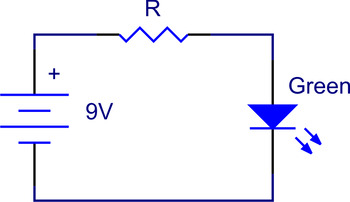
This circuit is very simple.

Simple basic schematic diagram. This may occur with or without their making. A schematic diagram is a picture that represents the components of a process device or other object using abstract often standardized symbols and lines. Use the concept of conventional current to draw an unbroken line on the schematic diagram at the right that indicates the direction of the conventional current.
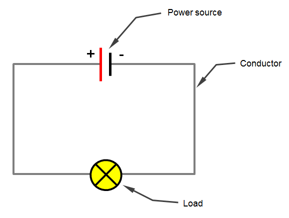
As shown in the diagram the power supply to the load is through the switching circuit and therefore the power supply can be cut by keeping the switch open. Simplediagrams is easy to use and good for lots of stuff. For a small led lamp normally we use a dc supply battery.
With plugin shape and background libraries the possibilities are endless. A schematic style circuit diagram is used to give a visual representation of an electrical circuit to an electrician. Basic components for this tutorial include an led resistor and battery which can all be found in the beginners component reference.
A schematic is defined as a picture that shows something in a simple way using symbols. The conductor is the roadway of the circuit map. The battery has two points anode and cathode.
The pictorial style circuit diagram would be used for a broader less technical audience. A desktop app for creating fast clear sketches of problems processes workflows ideas and more. After a four part introduction the first tutorial in the electronics course shows the circuit diagram of a simple led and resistor circuit and how to build it on breadboard.
These two different types of circuit diagrams are called pictorial using basic images or schematic style using industry standard symbols. Place an arrowhead on your. Create simple visualizations to communicate your ideas to your team students or clients.
Conductors often cross paths with one another in the circuit. Check your understanding 1. The conductors interconnect the components of the circuit.
Use circuit symbols to construct schematic diagrams for the following circuits.

 Pololu Simple Led Circuit
 3 Simple Audio Mixer Circuits Diagram Eleccircuit Com
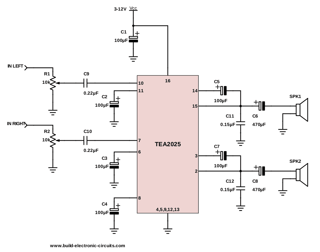 The Simplest Audio Amplifier Circuit Diagram
 Perfect Wiring Diagram Simple Basic Circuit Schematics 15 19
Simple Schematic Diagram Symbols Wiring Diagram E7
 Electrical Circuit Basics 12 Volt Planet
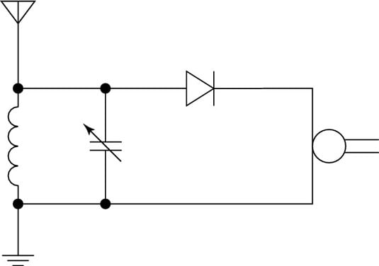 Electronics Projects A Simple Crystal Radio Circuit Dummies
 Schematic Diagram Showing The Basic Concept Of A Simple
 Simple Switch Wiring Diagram Wiring Diagram

 Simple Metal Detector Circuit With Applications Metal Detector
 Simple Siren Circuit
 Ac Motor Control Circuits Worksheet Ac Electric Circuits
 The Circuit Of A Simple Radio Receiver 9 Download Scientific

 A Simple Schematic Drawing Tutorial For Eagle Build Electronic
 944db Simple Schematic Diagram Digital Resources
No comments:
Post a Comment