Saturday, April 28, 2018

Schematic Diagram Of Auto Transformer Starter

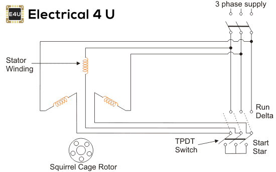
Star delta starter control circuit diagram. Autotransformer starter autotransformers can be used as a method of soft starting induction motors.

Autotransformer Starter Wiring Diagram Free Download Arresting

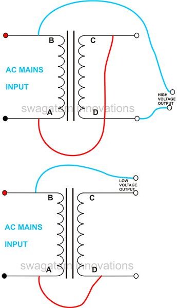
Auto transformer an auto transformer is a transformer with only one winding wound on a laminated core.

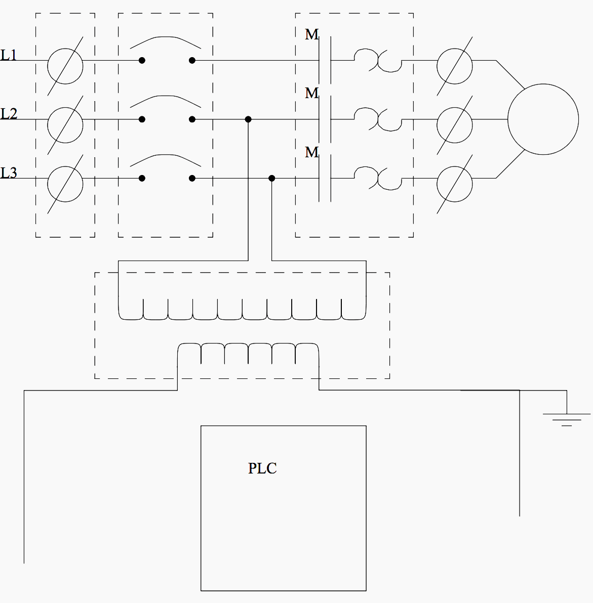
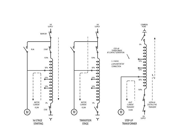
Schematic diagram of auto transformer starter. Auto transformer starter control wiring and power wiring diagram kaise kare duration. Most of the auto starters are provided with 3 sets of taps so as to reduce the voltage to 80 65 or 50 percent of the line voltage to suit the local conditions of supply. The inrush current in wye is reduced to 33 of what it would be if the motor was started with an across the line starter.

Assortment of 3 phase motor starter wiring diagram pdf. What is auto transformer starter. An auto transformer is similar to a two winding transformer but differ in the way the primary and secondary winding are interrelated.

3 phase motor starter wiring diagram pdf. Circuit and function an auto transformer starter makes it possible to start squirrel cage induction motors with reduced starting current as the voltage across the motor is reduced during starting. Ryb electrical 450141 views.

In this method the starting current is limited by using a three phase auto transformer to reduce the initial stator applied voltage. In contrast to the star delta connection only three motor leads and terminals are required. A part of the winding is common to both primary and secondary sides.

Pearl engineering 1674 views. One of the well known designs of such starters is korndorfer starter and x ray detectors. Auto transformer starter an auto transformer starter is suitable for both star and delta connected motors.

Circuit diagrams wye delta wye delta open transition stop start the wye delta open transition starter starts the motor by closing the s and 1m contactors which energize the windings in wye. The auto transformer starters can be used for both star and delta connected motors. Star delta connection duration.

The figure below shows the motor with the auto transformer starter. It shows the parts of the circuit as simplified shapes and also the power and also signal links in between the tools. A wiring diagram is a streamlined conventional photographic representation of an electrical circuit.

The auto transformer reduces the current in the mains supply line further and in accordance with its ratiothe technique for connecting an auto transformer stater is via magnetic contactor and connect the motor to taps by mean of the contactor.

Autotransformer And Variable Auto Transformer

Autotransformer Starter Diagram Working Explaination Youtube

Variable Transformer Wiring Diagram Free Picture Wiring Diagram E7

Motor Controls Natural Resources Canada

Auto Transformer Starting Of Squirrel Cage Rotor Induction Motor

58c8 Wiring Diagram For Auto Transformer Starter Wiring Library

What Is Auto Transformer Starter Working Principle Diagram Advantages

Diagram Wiring Diagram For Auto Transformer Starter Full Version

What Is Auto Transformer Starter Its Theory Circuit Globe

Korndorfer Autotransformer Starter Wikipedia

How To Start Squirrel Cage Induction Motors Electrical Engineering

Primary Resistor Type Starters Ac Reduced Voltage Starters

New Wiring Diagram Of Auto Transformer Starter Auto Transformer

What Are The Advantages Of Auto Transformers Quora

Motor Control Circuits Types Electrical Industrial

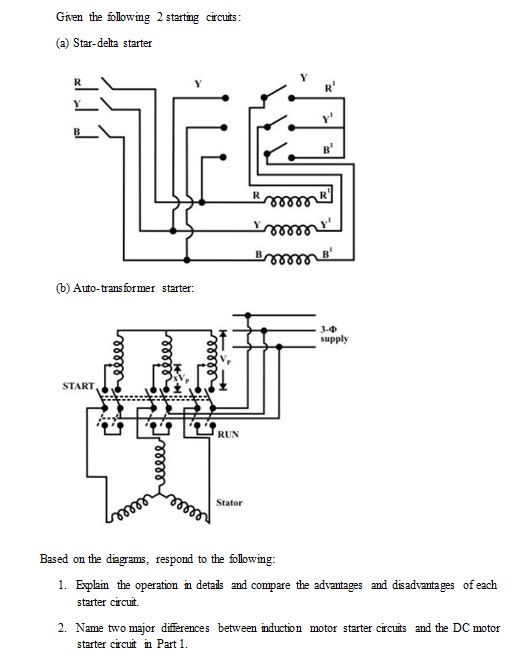
Solved 1 Explain The Operation In Details And Compare Th

Auto Transformer Starter Panel Cr4 Discussion Thread

Star Delta Starter Circuit Diagram Working Principle Theory

Controlling Motor Starting Wiki Odesie By Tech Transfer


Schematic Diagram In Research Paper Example

Chemists Invent Paper Based Low Cost Portable Ion Selective

Optimalization Of Extraction Conditions For Increasing Microalgal

How To Write And Format A White Paper With Examples

Figures Tables References

Schematic Of Paper Based Elisa For Detecting Dwv In V

Uncovering The Research Process Of International Students In North

Schematic Representation Of Experimental Method Associated With

Following Wiring Diagrams Youtube

Basic Electrical Design Of A Plc Panel Wiring Diagrams Eep

Block Diagram Wikipedia

Block Diagram Learn About Block Diagrams See Examples

Elements Of A Theoretical Framework

Scientific Papers Learn Science At Scitable

24 Theoretical Conceptual Framework The Theoretical Conceptual

Definition Of Schematic Diagram Chegg Com

Write My Research Paper Citingdissertations Web Fc2 Com

How To Read Circuit Diagrams 4 Steps Instructables

Schematic Diagram Of A Single Phase H Bridge Vsc Along With Its

35 Schematic Diagram In Research Paper

Using Graphic Organizers For Writing Essays Summaries And


Friday, April 27, 2018

Schematic Diagram Geothermal Power Plant

Heat from the earth or geothermal geo earth thermal heat energy is accessed by drilling water or steam wells in a process similar to drilling for oil. The steam that is extracted is channelled into steam pipelines and forwarded to a turbine where the kinetic energy of the steam is transformed into rotational mechanical power.

Geothermal Power Wikipedia

Geothermal power station diagram.

Schematic diagram geothermal power plant. The diagram illustrates the process by which geothermal energy is used in the production of electricity. The layout of the geothermal power plant illustrates the whole process from heated water and steam in the depths until electricity powering our homes. Most power plantswhether fueled by coal gas nuclear power or geothermal energyhave one feature in common.

The diagram outlines the basic design of a dry steam power plant one of the oldest designs dating back to the early 1900s. Delighful simple geothermal energy diagram this at with geothermal power plant schematic diagram image size 500 x 364 px and to view image details please click the image. The simplicity of this design ensures dry steam power plants are highly efficient even in todays environment.

Generator turbine production well geothermal zone injection well air and water vapor air water waste brine steam direct heat uses c1994 2020 smartdraw llc. With such a mathematic model both the capacity and efficiency of the power plants are calculated. Power plant company name drawn checked date drawing no.

People use these resources by drilling wells into the earth and then piping steam or hot water to the surface. Of geothermal power generation with a flash system combined with binary cycle and suggests a mathematic model of thermodynamic calculation for such combined geothermal power plants in detail. Diagram of a geothermal power plant through the fractures in the layers of rock water and steam which has been heated in the depths rise to the surface and are intercepted in the geothermal wells.

Schematic diagram of a double flash condensing system of the bouillante geothermal power plant located at the coast of the island basse terre south of thebouilanteinguadeloupe mixtureof 20to80. Geothermal power plants require high temperature 3000f to 7000f hydrothermal resources that come from either dry steam wells or from hot water wells. They convert heat to electricity.

Overall there are five steps in the process starting from pumping down cold water into the geothermal zone to producing electricity from the generator which is then sent into the electrical grid. The steam was extracted from the different layers of the earth and channeled into steam pipelines to be forward to the turbines. Here is a picture gallery about geothermal power plant schematic diagram complete with the description of the image please find the image you need.

Below is a diagram of a geothermal power station. In the first step. Geothermal power plant diagram.

The results are given in a diagram which.

What Is Geothermal Energy Quora

Https Aip Scitation Org Doi Pdf 10 1063 1 4941863

Geothermal Energy

Geothermal Power Conversion Technology Springerlink

File Schematic Doubleflash Geothermal Powerplant Eng Png

Solved Problem 3 The Schematic Of A Single Flash Geother

Solving Africa S Energy Poverty Problem Part 5 Geothermal

A Schematic Diagram Of A Geothermal Condensing Power Plant

Https Pangea Stanford Edu Ere Db Wgc Papers Wgc 2015 26006 Pdf

Block Diagram Of Sumikawa Geothermal Power Plant Japan

Sustainability Free Full Text Improving The Environmental

Https Geothermalcommunities Eu Assets Elearning 7 2 Power From Ge Pdf

Geothermal Energy Resources

File Schematic Geothermal Binary Powerplant Eng Png Wikimedia

Simplified Schematic Of Flow Diagram For A Single Flash Power

Geothermal Power Plant

Figure 13 From Response To The Comments By Ronald Dipippo On

Vapour Dominated Geothermal Power Plant Energy Management

Https Geothermalcommunities Eu Assets Elearning 7 2 Power From Ge Pdf