It represents a complex application where accurate measurement correct instrumentation power manager and signal integrity are a critical factor for correct operation of a machine which a human life may depend on. Nellcor mallinckrodt and puritan bennett might be the same.
Piston Ventilator
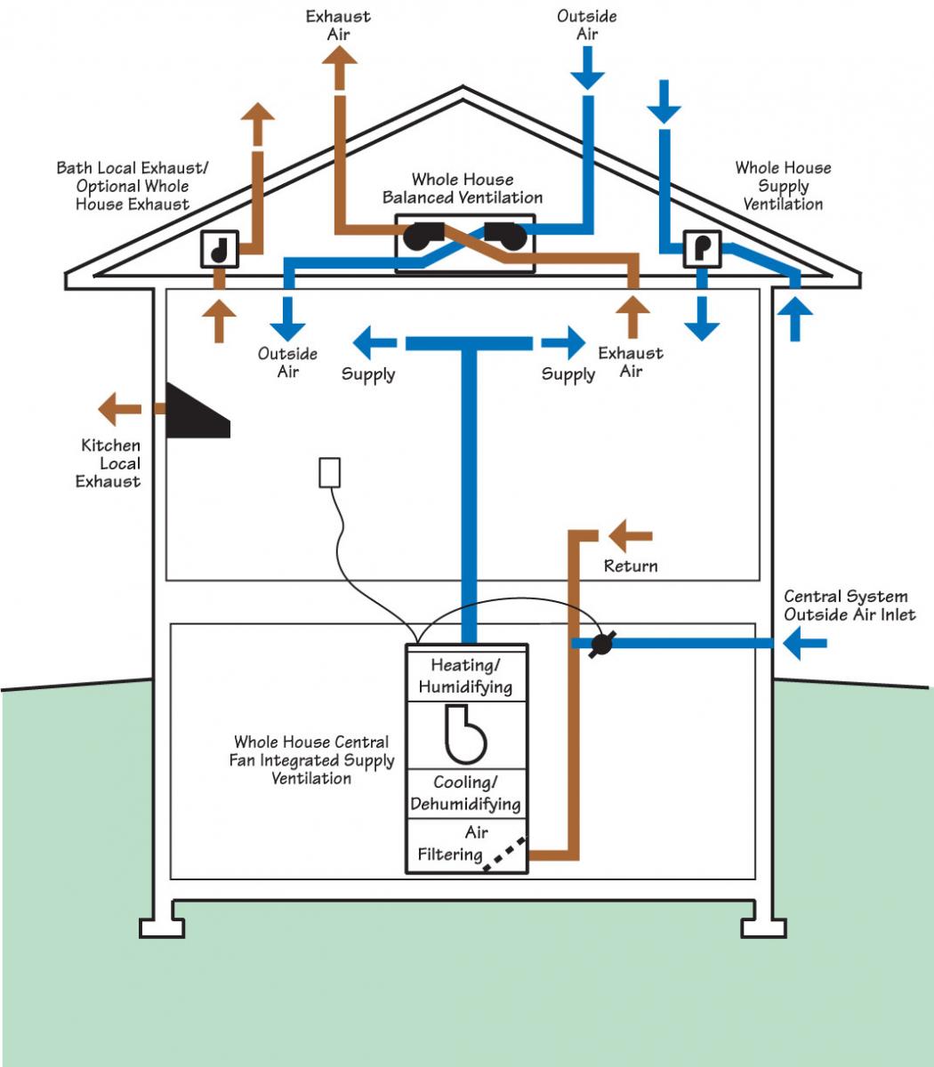
These are excellent options when your sink is too far away from the main stack.
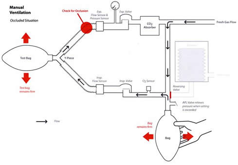
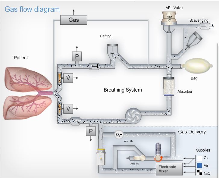
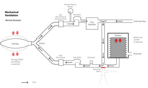
Schematic diagram of ventilator. Air ducts friction loss diagram. It provides information related to breathing circuit positioning and maintenance of related components. About that time the average clinician could also completely disassemble and reassemble a mechanical ventilator as a training exercise or to perform repairs.
Ventilatorrespirator hardware and software design specification rev. Other times the patient cannot breathe at all and the ventilator is set to take over what would be the patients regular breathing pattern. Major loss diagram for air ducts si units.
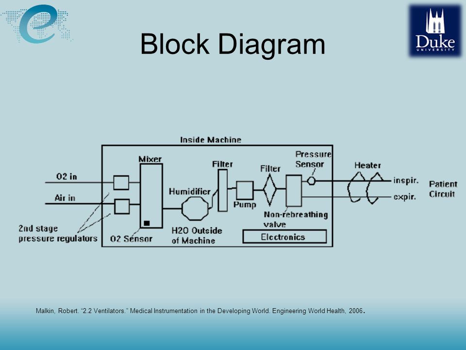
Major loss diagram for air ducts in imperial units ranging 10 000 400 000 cfm. In those days the late 1970s textbooks 1 describing ventilators understandably paid much attention to the individual mechanical components and pneumatic schematics. A ventilator moves air into and out of the lungs oxygen in and carbon dioxide out.
Air flow and required duct area. A major loss diagram for air ducts imperial units ranging 10 100 000 cfm. This application note is intended as a useful reference for ventilation of adult and pediatric patients.
Compressors for mechanical ventilators see the medical gas supply section. Rough in plumbing diagram ask the builder a rough in plumbing diagram is a sketch drains and vent piping this plumbing diagram might be what is the max length of a 2 shower drain before unclog a bathtub drain step 28 version 7. 1 breathing circuit diagram the breathing circuit and components shown here are an.
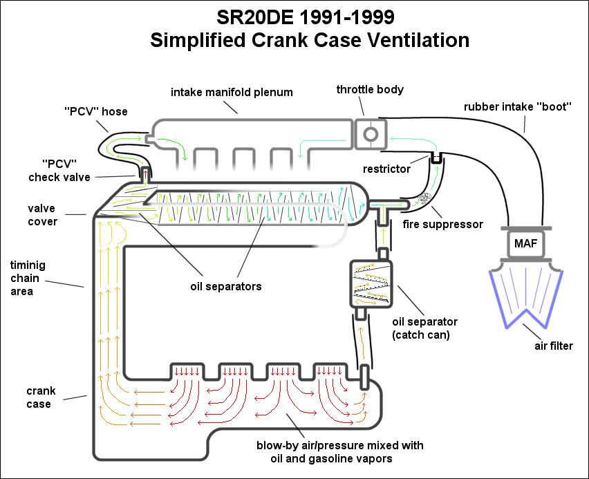
According to the definition offered by chatburn a mechanical ventilator is an automated machine in which. Re vent pipes otherwise known as auxiliary vents attach to the drain line near your fixture as they run upwards and over the main vent. Positive crankcase ventilation pcv diagrams and notes first published 2015 r.
Ventilators as stand alone equipment as part of anaesthesia machines homecare ventilators cpap and bipap airway humidifier and nebulizer. Added excerpt from factory drawing showing variations of pcv including b20a which were not imprted into the usa. Air ducts sizing.
How does a ventilator work. They can attach right behind your fixture or horizontally to the drain line. Energy is transmitted or transformed by the ventilators drive mechanism in a predetermined manner by the control circuit to augment or replace the patients muscles in performing the work of breathing.
Air ducts friction loss diagram.
 Hrv Erv Prairie Design Build
Measurement Of Expiratory Limb Circuit Pressure A Potential
 Chapter 3 Basic Principles Of Ventilator Design Principles And
 Ventilators Who Ventilator Intensive Care Neonatal Pediatric
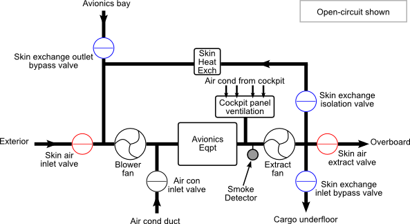 5 Avionics Ventilation
 Measurement Of Expiratory Limb Circuit Pressure A Potential
 Ventilator Vt Plus Hf Gas Flow Analyzer Dr Fadhl Al Akwaa Please
 Exhalation Valve An Overview Sciencedirect Topics
 Image Result For Isometric Drawing Ventilation System Piping And
 Automotive Crankcase Ventilation Systems Diagram Pcv


 Pre Retrofit Assessment Of Ventilation Systems Building America
 Figure 1 From A Dual Closed Loop Control System For Mechanical
1585437495000000
 Chapter 3 Basic Principles Of Ventilator Design Principles And
 Schematic Of The Ventilator Circuit And Respiratory Tract

No comments:
Post a Comment