Here is a picture gallery about fire pump wiring diagram complete with the description of the image please find the image you need. Y 07x 170 x flow expressed as a percentage of rated flow y pressure created by the pump net pressure expressed as a percent of rated pressure 93.
Schematic diagram for a fire pump installation sts 15 ref.

Fire pump schematic diagram. Today you can expect to find a fire pump in almost any public building or factory. In both manual and automatic modes the pumps. A wiring diagram is a simplified standard pictorial representation of an electric circuit.
Battery operated sump pump installation. Since fire pumps are considered life safety equipment they must be reliable. Keep in mind that your fire engines pump and plumbing will have a different configuration and may not be equiped with all the valves listed.
Take apart our fire suppression equipment with the click of your mouse. Best part its free and ready for your assembly. Designing electrical systems for fire pumps.
Fpo 89 december 1999. Fire pump controllers. Its really that simple.
It reveals the elements of the circuit as simplified shapes and the power as well as signal links between the tools. If you work with the connections or controls for fire pumps you need to understand article 695. 22830 dec mods.
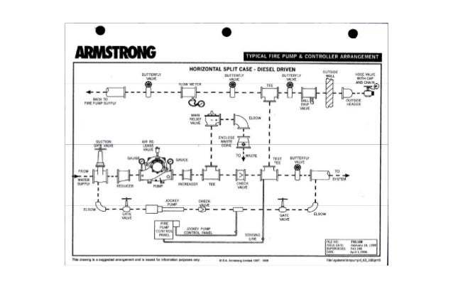
Control of the electrical and diesel driven fire fighting pumps the pumps shall be capable of operating in both manual and automatic modes but under no circumstances must they be able to start up or run simultaneously. Home technical information diagrams typical pump installations. This basic diagram was designed to help you understand the functionalty of a fire engines pump and plumbing.
Ecv variable speed controller. Fire pump sizing the estimated performance of the fire pump between 100 and 150 of rated flow can be calculated using the following formula. Watch a video example tour below or click the button to get started.
Collection of fire pump controller wiring diagram. Every fire engines plumbing is build differently. By mike holt for ecm magazine.
Submersible well pump accessories installation diagram. Fire and jockey pump controller sensing lines mike trumbature with regard to fire pump wiring diagram image size 797 x 612 px and to view image details please click the image. Cistern lake river or canal pump installation.
Options and miscellaneous. Find all fire pump controller drawings as well as jockey pump controller remote alarm panel and low suction shutdown controller drawings here. Index of products.
Fire hazard unsatisfactory performance and equipment failure. Article 695 fire pumps. When designing or installing electrical power supplies for fire pumps and their accessories you must apply special rules as listed in nfpa 70 the national electrical code nec and the standard for centrifugal fire pumps cfp nfpa 20.
 2d Diesel Fire Pump 3d Cad Model Library Grabcad
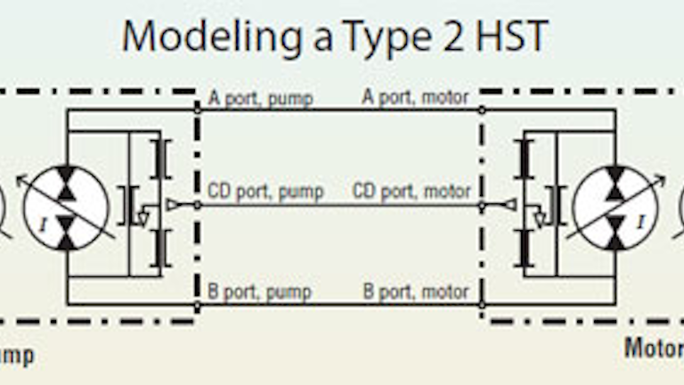 Understanding Hydrostatic Transmissions Hydraulics Pneumatics
Http Westmontlibrary Org Wp Content Uploads Monarch Fire Protection As Built Pdf
 Fire Pumps And Equipments Installation
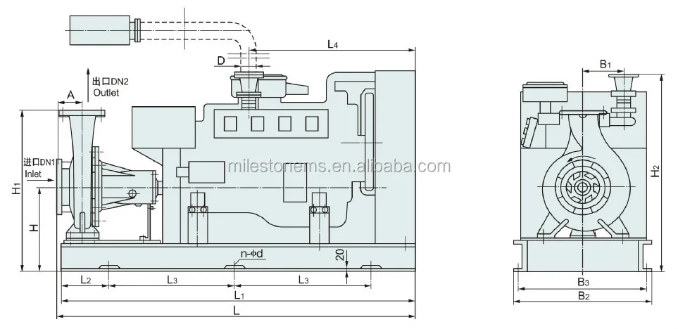 Cummins Driven Diesel Engine Fire Pump Buy Diesel Engine Fire
Https Files Nc Gov Ncdoa Documents Files Firepumpchecklist Pdf
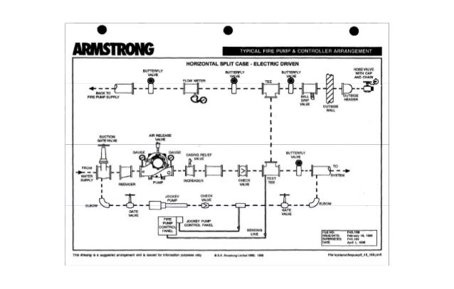 Nfpa20 Standard For The Installation Of Stationary Pumps For Fire Pro
Https Www Montgomerycountymd Gov Mcfrs Psta Resources Files Driver 20150325 Unitkbengines Engine Manual Training 20supplements 20spring 202019 Module 204 20 20centrifugal 20fire 20pumps Pdf
 Methods And Systems For Overcurrent Protection In A Fire Pump
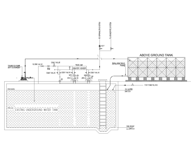 Need Advice On A Funny Design Received Nfpa Fire Code Issues
Http Www Markrobisonpe Com Wp Content Uploads 2008 12 Fire Pump Installs1 Pdf
 Nfpa20 Standard For The Installation Of Stationary Pumps For Fire Pro
 A Schematic Explaining The Heat Engine Invented By Savery To Pump
Fire Main System Onboard Ships For Fire Fighting
 Nema Application Guide For Electric Fire Pump Controllers
 C E T Pfp14hpkhl 1d 14 H P High Volume Fire Pump Manual Start
 Sc 1014 Page Titlefigure 7111 Space Heater Flow Diagram
No comments:
Post a Comment