Hs 20 65 booster pump systems with torrium 2 data brochure and catalog. Common pool plumbing layout for the pool spa combo design with booster pump cleaner line drawing off pool return line.
There is additional information on this web site for installation of the ro system.

Booster pump schematic diagram. Technically qualified personnel should install pumps and motors. Figure 3 1 illustrates schematic piping of two types. 1 boost water from elevated tank to water.
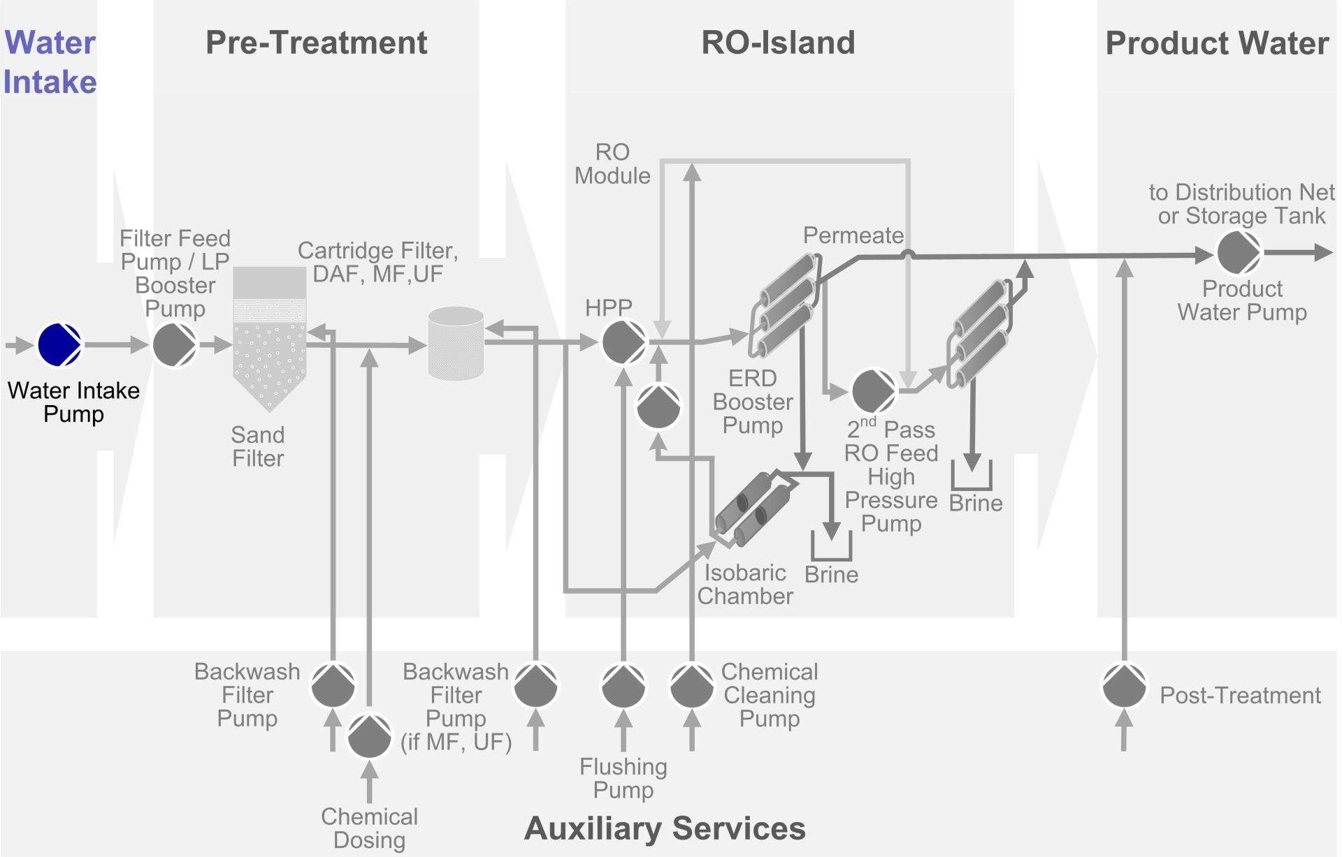
Laws on the proper use of booster pump. Diagram of a 4 stage reverse osmosis system with booster pump and permeate pump. Per standard regulation the use of booster pump is actually an allowed practice for water service concessionaires in instances when it is installed in the proper manner.
All information is provided as a courtesy to our customers. However existing laws and policies have strictly prohibited the improper. Capitol vacuum parts does not warrant the accuracy of the information provided by any pump manufacturer.
Booster pump wiring diagram as well as water booster pump schematic furthermore jaguar xjs vacuum line diagram along with p 0900c152801c0f6e also grundfos pump schematic along with t2109728 need diagram 1995 gmc safari v6 power moreover 1989 isuzu npr wiring diagram as well as baldor single phase wiring diagram. Diagrams typical pump installations. Solar pool plumbing diagram 5 jandy 3 way valves.
I just want to make sure if my booster pump schematic is correct. Pressure booster pumpsend suction pumpssh pressure booster pumpshakti pumpsinstallation videopump installationpressurewater pressurelearn pump installationpressure booster installation. I am designing a job for an oil field where a water booster pump set will be installed.
Click on instruction manuals and you can mouse down and locate the ro installation instructions. Booster pump may be above ground or underground. Hs series booster pump systems data brochure and catalog.
I have done loop and pressure calculations. The information provided here is for educational purposes only. For small booster pump applications as for remote housing or satellite.
Pump and controls selection for in line booster pumps will consider minimum suction pressure and automatic discharge cut off pressure. Hs series booster pump systems installation and operating instructions guide. Schematic diagram on the proper use of booster pumps a.
It is a labor camp of 200 people with an elevated tank in a desert. Please check with the pump manufacturer for updated information. This pump will have two functions.
Click on the pdf emblem and you will be transferred to the diagram.
 Schematic Diagram Of The New System With One Booster Pump For Each
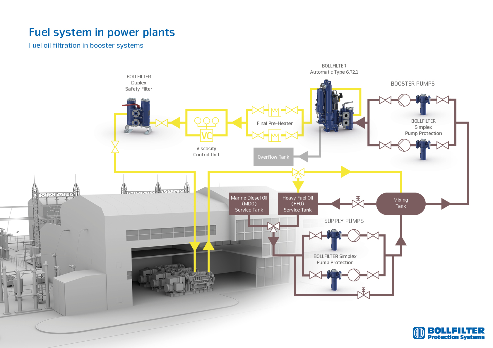
 Power Plant Fuel Oil Filtration In Booster System
 Pool Supply Unlimited Pentair Letro Universal Booster Pump 75hp
 Sprinkler System Booster Pump Addition Doityourself Com
 Booster Pump Installation Google Search Mechanical Design
H2osplashwaterfilters Water Filter University
Jandy Valve Plumbing Schematics Inyopools Com
 Booster Pump Installation Google Search Installation Well
Jet Pumps Centrifugal Pumps Installation Shallow Well Or Deep Well
 Figure 1 From Experimental Solubility Of Co2 And Ch4 In
 Float Switch Installation Wiring Control Diagrams Apg
 Bt Series Booster Pump System Rainwater Management Solutions
 Schematic Diagram Of Aero Engine Fuel Centrifugal Pump Test Rig
 A Schematic Diagram Of The High Pressure High Temperature Gas
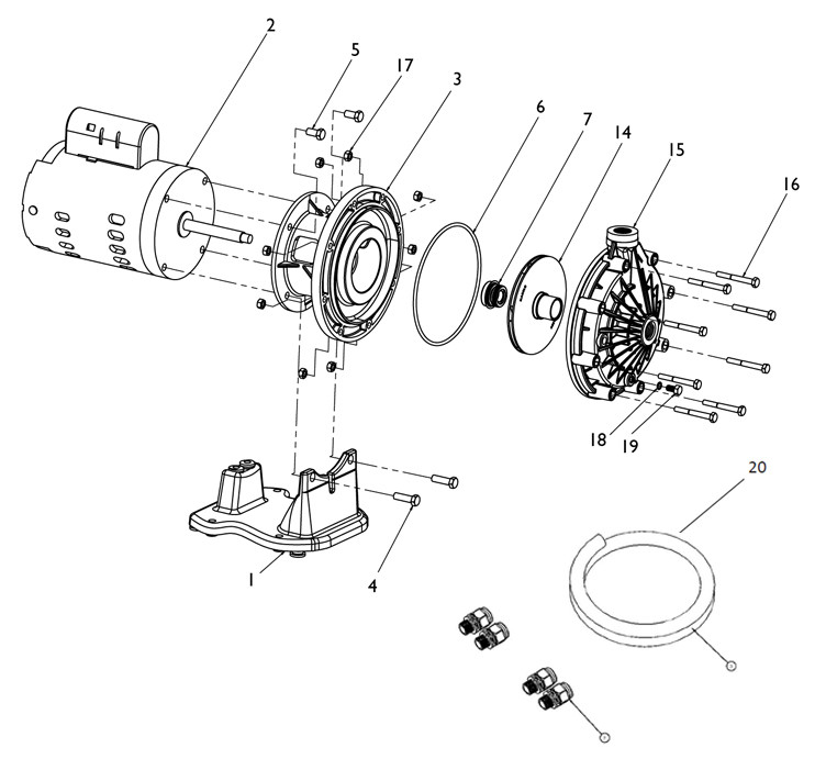
 Pentair La01n Booster Pump Replacement Parts
 Pressurized Freshwater Systems West Marine
Dff4 Water Tank Schematic Wiring Library


No comments:
Post a Comment