Components of an electrical submersible pumping system source. It shows the elements of the circuit as simplified forms and also the power as well as signal links between the devices.
 Schematic Of A Submersible Pump Deep Well System C Carson Dunlop
It shows the elements of the circuit as streamlined forms and the power and signal connections in between the devices.
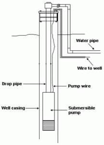
Submersible pump schematic diagram. Api rp 11s3 the pump discharge head. The pump housing is a cylinder 35 in. The pump and the motor are contained in one housing submersed below the permanent water level within the well casing.
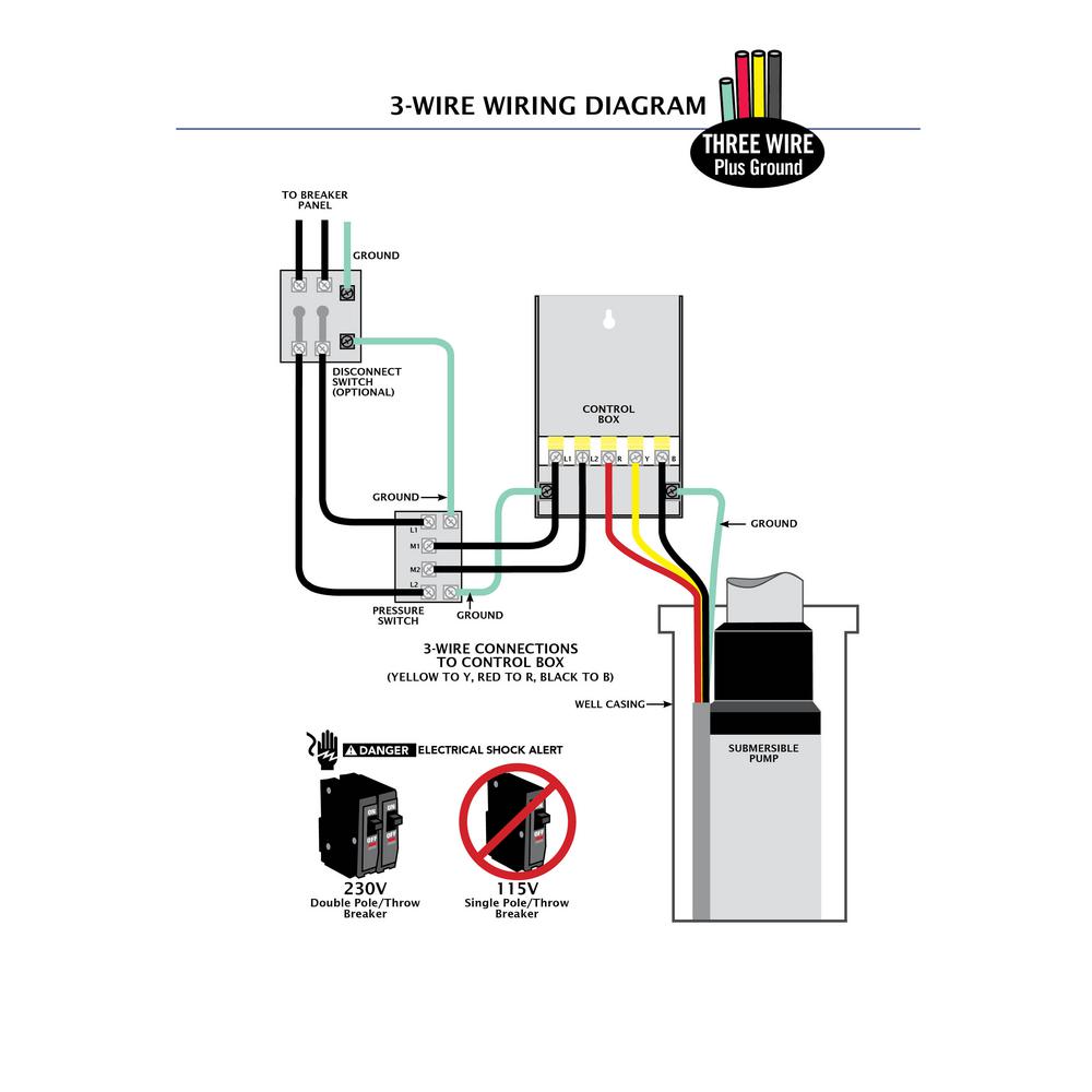
A guide of 3 phase submersible pump wiring diagram with direct online starter using contactor mccb overload relay and push button switches. 3 wire submersible pump wiring diagram. Collection of submersible pump control box wiring diagram.
Submersible pump control box wiring diagram. Single phase submersible pump control box wiring diagram 3 wire submersible pump wiring diagram. The wiring connection of submersible pump control box is very simple.
The pump discharge head is usually a separate component that bolts onto the top of the pump section. Getting from point a to point b. Collection of 3 wire submersible pump wiring diagram.
A wiring diagram is a simplified traditional photographic depiction of an electrical circuit. The following figure shows schematic diagram of a submersible pump installation. 2 wire submersible well pump wiring diagram a newbie s overview of circuit diagrams a very first look at a circuit layout could be complicated however if you can review a subway map you could read schematics.
The purpose is the very same. In diameter and 24 ft long. Electrical online 4u a platform to learn electrical wiring single phase 3 phase wiring controlling hvac electrical installation electrical diagrams.
A submersible pump consists of a centrifugal pump driven by an electric motor. Submersible pumps basic information and diagram. In submersible pump control box we use a capacitor a resit able thermal overload and dpst switch double pole single throw.
A wiring diagram is a streamlined traditional photographic representation of an electrical circuit.
 Well Pump Schematic Wiring Diagrams Blog
 Automatic Water Tank Filler Circuit Diagram Eeweb Community
 Eco Flo 1 Hp Control Box For 4 In Well Pump Efcb10 Hd The Home

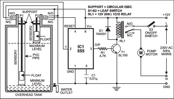 Automatic Water Level Controller Detailed Circuit Diagram Available

 Automatic Submersible Pump Controller Circuit With Dry Run Protection
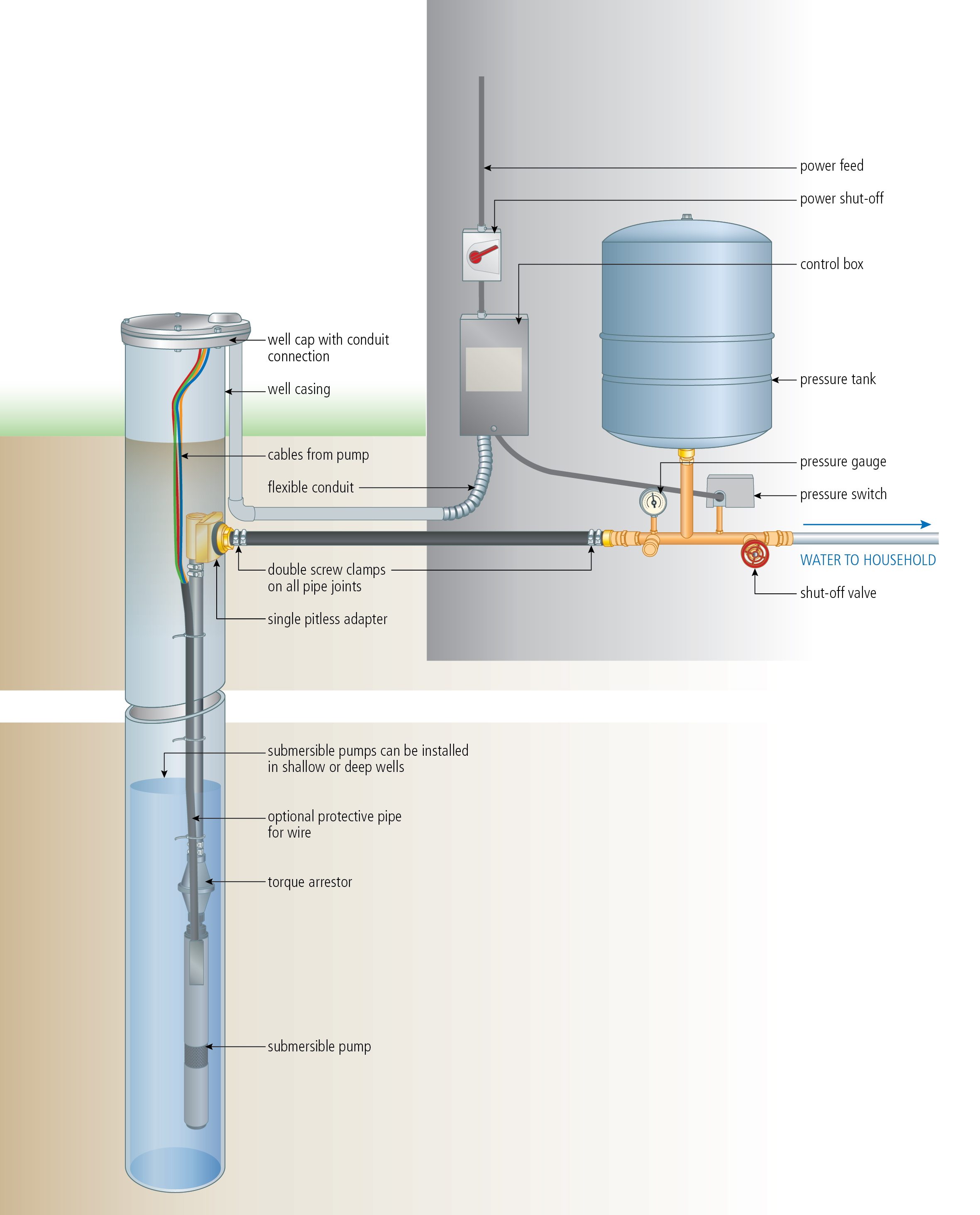 Install A Submersible Pump 6 Lessons For Doing It Right
 Wiring Diagram For 220 Volt Submersible Pump Well Pump Pressure
![]() How To Create A Pump Control Circuit To Automatically Empty A Tank
How To Create A Pump Control Circuit To Automatically Empty A Tank
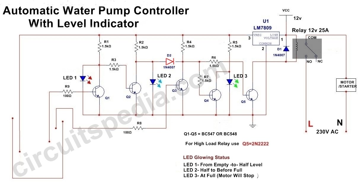 Automatic Water Pump Controller Circuit With Indicator
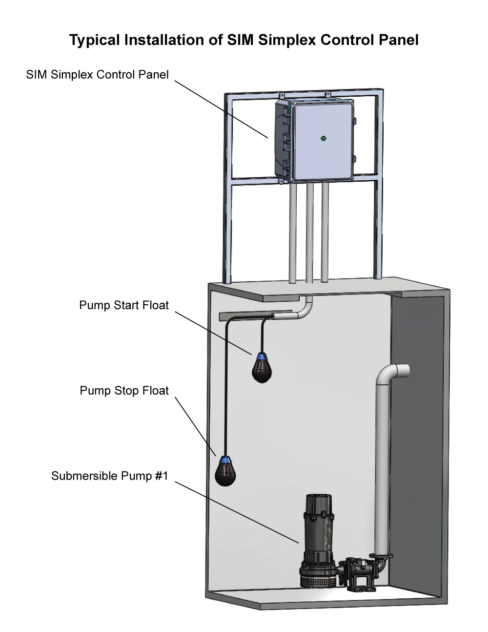 Sim Single Phase Simplex Pump Control Panel Wastewater Panel
![]() Solar Pump Block Diagram Types Advantages And Disadvantages
Solar Pump Block Diagram Types Advantages And Disadvantages

 Schematic Lateral Diagram Of The Facility 1 Low Tank 2 High
 Automatic Water Pump Control Testing Youtube
 Air Cooler Water Pump Guard
 Aim Manual Page 54 Single Phase Motors And Controls Motor

No comments:
Post a Comment