When a liquid converts to a gas in a process called phase conversion it absorbs heat. Schematic diagram configurations there are two basic configurations used in schematics today to show the approximate placement of loads switches and different power or supply voltages.
 Hvac Compressor Wiring Wiring Diagram E7
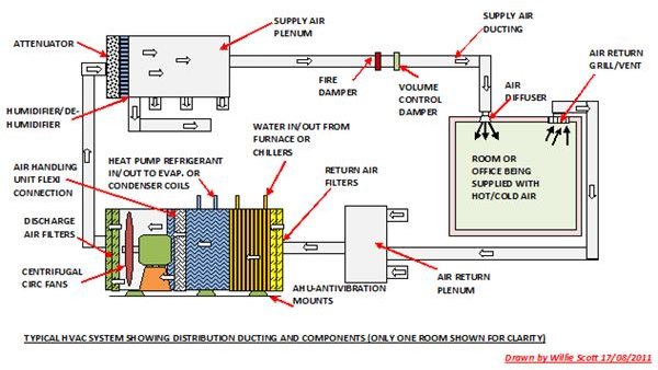
The air conditioning system includes the following components.

Basic hvac schematic diagram. Once finished the drawing can be saved and exported into standard formats in edraw max including word excel ppt svg jpg tiff png html etc. Air conditioners use refrigeration to chill indoor air taking advantage of a remarkable physical law. The main electrical components in hvac equipment are fan motors compressors and devices like gas valves and solenoid valves.
Air conditioners exploit this feature of phase conversion by forcing special chemical compounds to evaporate and. If you have a two stage heat pump then you will also utilize terminal y2 for the second stage. All of these are electrical loads.
The first is a side by side arrangement an example of which is shown in figure 9. Schematic and ladder diagrams. Learn from the experts at standard heating.
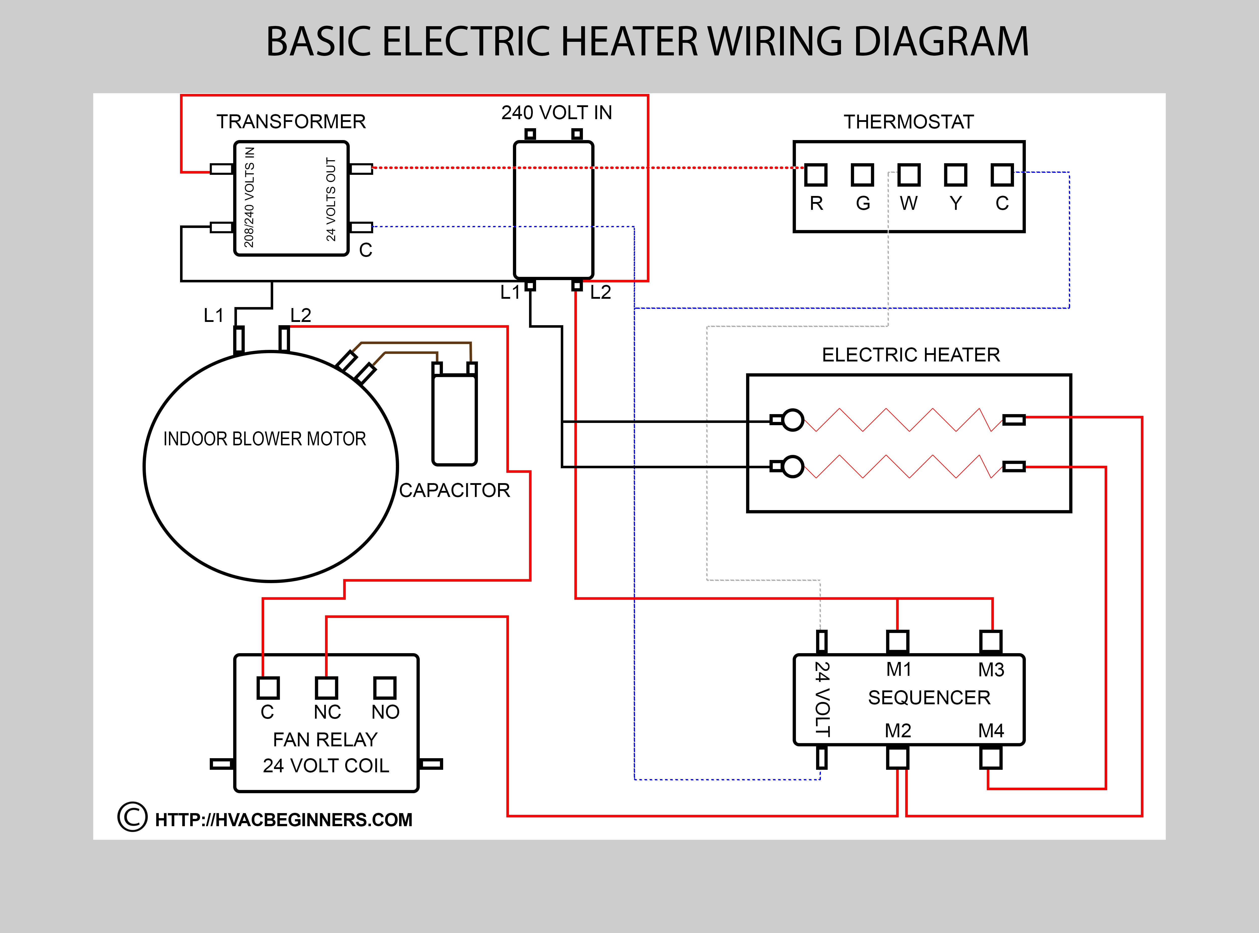
Most ladder diagrams show the following basic components. A load is a component in a circuit that converts electricity into light heat or mechanical motion. Wiring diagrams for hvac systems and other complicated electrical systems come in two major variations schematic diagrams and ladder diagrams.
Where the power supply is what path the power takes the load component the switch component and a legend for the symbols used in the diagram. Hvac diagram our hvac diagram helps you understand the different components of your residential heating and cooling system. That is a basic honeywell thermostat wiring diagram for a single stage heat pump.
All these hvac symbols are free for use with edraw hvac maker. The first is a side by side arrangement an example of which is shown in figure 9. If you have a two stage heat pump then you will also utilize terminal y2 for the second stage.
Manufactur ers usually place motors and other power consuming. Schematic diagram configurations there are two basic configurations used in schemat ics today to show the approximate placement of loads switches and different power or supply volt ages. Hvac control systems also contain switches and other control devices.
Because it explains electrical circuits the diagram looks like a ladder which is where the name comes from. Of the two types of diagrams the ladder types are perhaps the easier of the two to understand especially for the beginner. The outdoor condenser unit is not the only part of your ac.
You can easily drag and drop any symbols on the canvas to make an hvac plan.
 Basics Of Drawing Schematics In Solidworks Electrical 2d
 Thermostat Wiring Diagrams Wire Installation Simple Guide
Everything You Need To Know About Hvac Systems
 Hvac Upgrades To Improve Efficiency
 Simple Hvac Schematic Diagram Wiring Diagram

 Ladder Diagram Basics 1 Youtube
 Hvac System Hvac Water Chillers Water Chillers
 Hvac Wiring Schematics Wiring Diagrams
 What Is Hvac System Hvac System Working Principle
 The Schematic Diagram Of The Investigated Hvac System Hvac
 Hvac Wiring Schematics Wiring Diagrams
 Wiring Diagram Symbols Hvacr Wiring Diagram E7
 Hvac Training Schematic Diagrams Youtube
 Heat Sequencer Wiring Diagram Wiring Diagrams
Everything You Need To Know About Hvac Systems
 Hvac Diagram Standard Heating Air Conditioning
No comments:
Post a Comment