There are three ways to show electrical circuits. If you are trying to describe an electrical circuit to your friend or neighbor it is likely that you have to draw the connection.
 Electrician Electrical Engineer Drawing
Types of electrical diagrams or schematics.

Electrical engineer schematic diagram electrical circuit. Electrical symbols are used to represent various electrical and electronic devices in a schematic diagram of an electrical or electronic circuit. For example if you want to explain a lighting circuit. The symbols represent electrical and electronic components.
Electrical symbols and electronic circuit symbols are used for drawing schematic diagram. The following table lists some basic electrical symbols in our electrical drawing software. Completing an electrical engineering degree and then getting a job in the field means you will see a lot a lot a lot of these schematics.
Every electrical engineering student needs to work with energies such as solar energy geothermal energy wind energy gas and turbine etc. They are wiring schematic and pictorial diagrams. You can enter shape data and add new data to a shape.
An electrical circuit is a closed loop in which continuous electrical current goes from the supply to the load. Electrical wiring diagram and electrical circuit diagram both are different they are not the same. Drag electrical component shapes onto the drawing page.
In the define shape data dialog box click in each item and type or select a value. A schematic circuit diagram represents the electrical system in the form of a picture that shows the main features or relationships but not the details. 10 common electrical symbols found on electrical schematic diagrams these symbols might look like nonsense to the layman but they provide a ton of information to the ee an electrical schematic diagram might look like a nonsensical drawing to the layman but to the electrical engineer its a high level documentation that provides a ton of.
The uses of these two types of diagrams are compared in table 1. Electrical symbols electronic symbols. Its important to understand exactly what is going on with these.
Electrical engineering is a branch of engineering that involves a different power or energy form to run the entire world. Shapes can have data. While they can and will get very complex these are just a few of the common graphics to get your footing on.
The two most commonly used are the wiring diagram and the schematic diagram. Today we are going to know what is the electrical wiring diagram what is the electrical circuit diagram and the difference between wiring diagram and circuit diagram or electrical schematic diagram. Free electrical mini projects ideas with circuit diagrams.
In a schematic circuit diagram the presentation of electrical components and wiring does not entirely correspond to the physical arrangements in the real device. Select a shape right click click data and then click define shape data.
 Star Delta Wiring Diagram Electrical Engineering Electrical
 484db Komatsu Solenoid Wiring Diagram Wiring Resources
 Free Electrical Projects With Circuits For Engineering Students
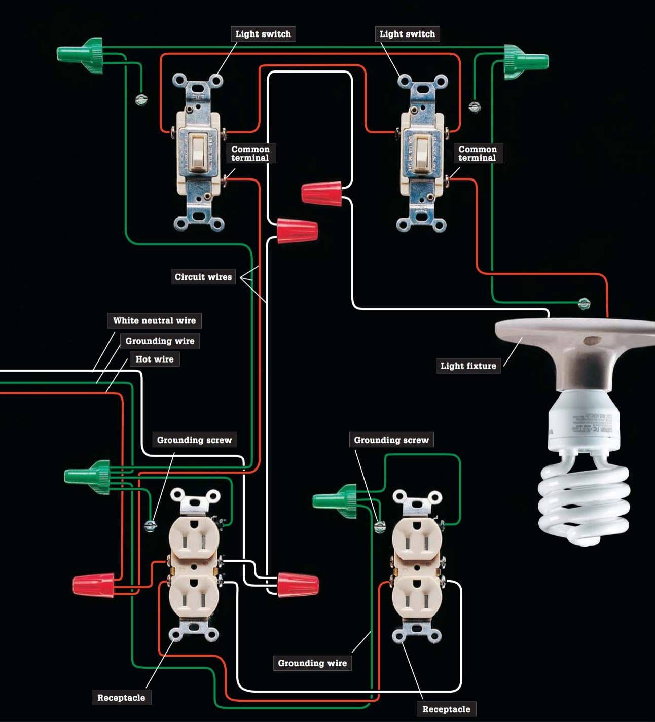 The Complete Guide To Electrical Wiring Eep
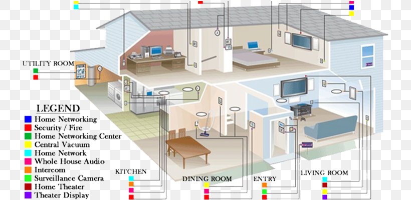 Wiring Diagram Home Wiring Electrical Wires Cable Schematic Png
 Electrical Schematic Installation Diagram Wiring Diagram
 What Is The Difference Between Schematic Diagram And Wiring
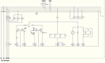 Electrical Drawings And Schematics Course Zoe Talent Solutions
 Engineering Symbology Prints And Drawings Module 3
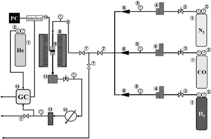
 A Schematic Diagram Of The Electrical Part Involving 1 Computer
 How To Read An Electrical Diagram Lesson 1 Youtube
 Electrical Print Reading Industrial Wiki Odesie By Tech Transfer
 5de
5de
 Schematic Wikipedia
 Electrical Symbols Composite Assemblies
 Star Delta Starter Electrical Circuit Diagram Electrical
 Electrical Diagrams And Schematics Wiki Odesie By Tech Transfer
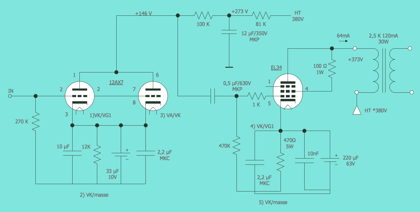 Engineering Electrical
 Electrical Engineering Designing Services Electrical Cad Drawings

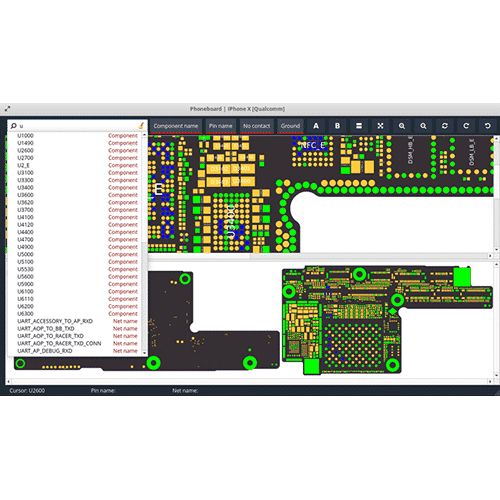 Zxw Board Diagram Schematic Software 1 Year Online Account Nugsm
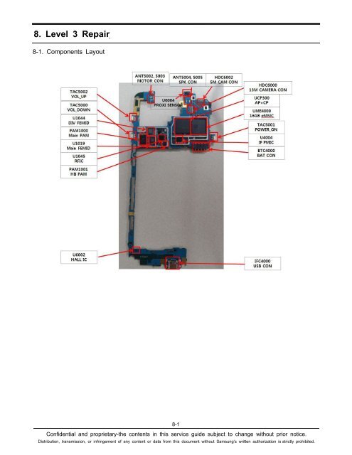
 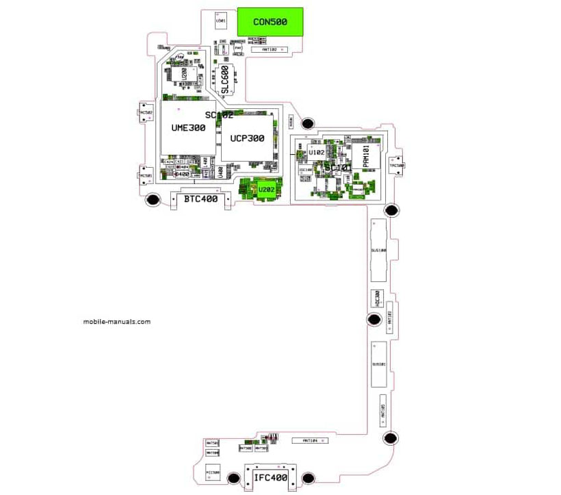 Galaxy J Schematics Schematics Service Manual Pdf
  Esquema Eletrico Samsung Galaxy J6 J600 F 2018 Celular
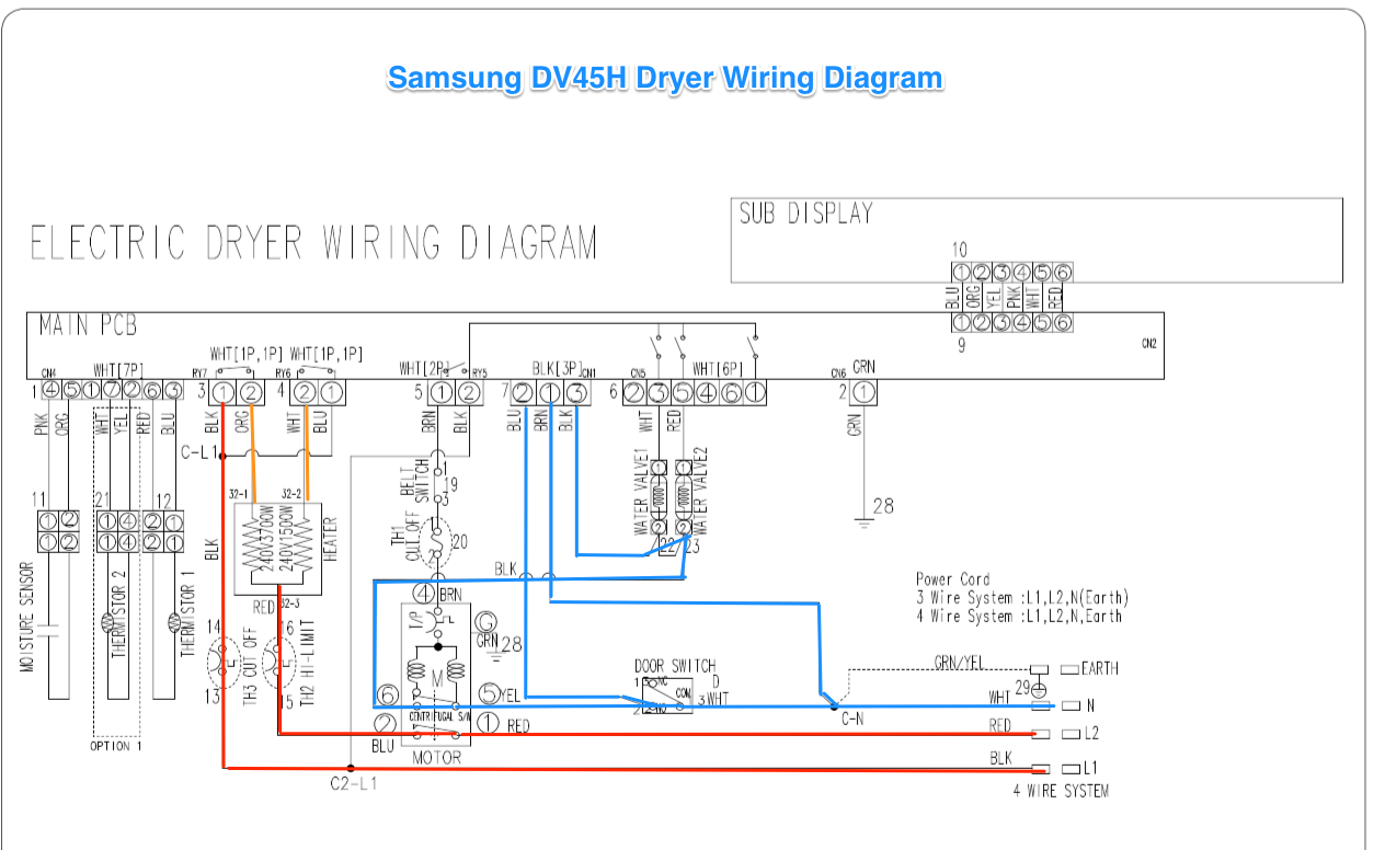 1c34 Ge Dryer Wiring Schematic Wiring Resources
  Samsung Pdf Schematics And Diagrams Schematic Diagrams User S
  Samsung Galaxy J6 2018 Service Manual Sm J600f Sm J600fn Sm
  Samsung J6 J600f Fingerprint Problem Solution Fingerprint Ways
 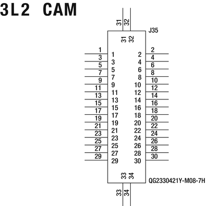 Developer Reference Boards Springerlink
  Download Samsung Galaxy J6 Plus Sm J610f Fn G Pie 9 0 One Ui Stock
  Download Phone S Manual Samsung Galaxy J6 Plus 4g Virgin
Lavairis600 Mobile Phone Schematics Sp41 Ddr2 Mb V1 0 20150707 162
 Galaxy J User Manuals Schematics Service Manual Pdf
  30 Charger Ac Adapter Compatible Samsung Galaxy J8 J7 J6 J6 J5 J4
  Samsung Pdf Schematics Circuit Diagram Free Manuals


