Simple car circuit breaker schematic diagram circuit and wiring diagram download for automotive car motorcycle truck audio radio electronic devices home and house appliances published on 17 mar 2014. Figure 11 wiring diagram of a cars electrical circuit.
 Boat Building Standards Basic Electricity Wiring Your Boat
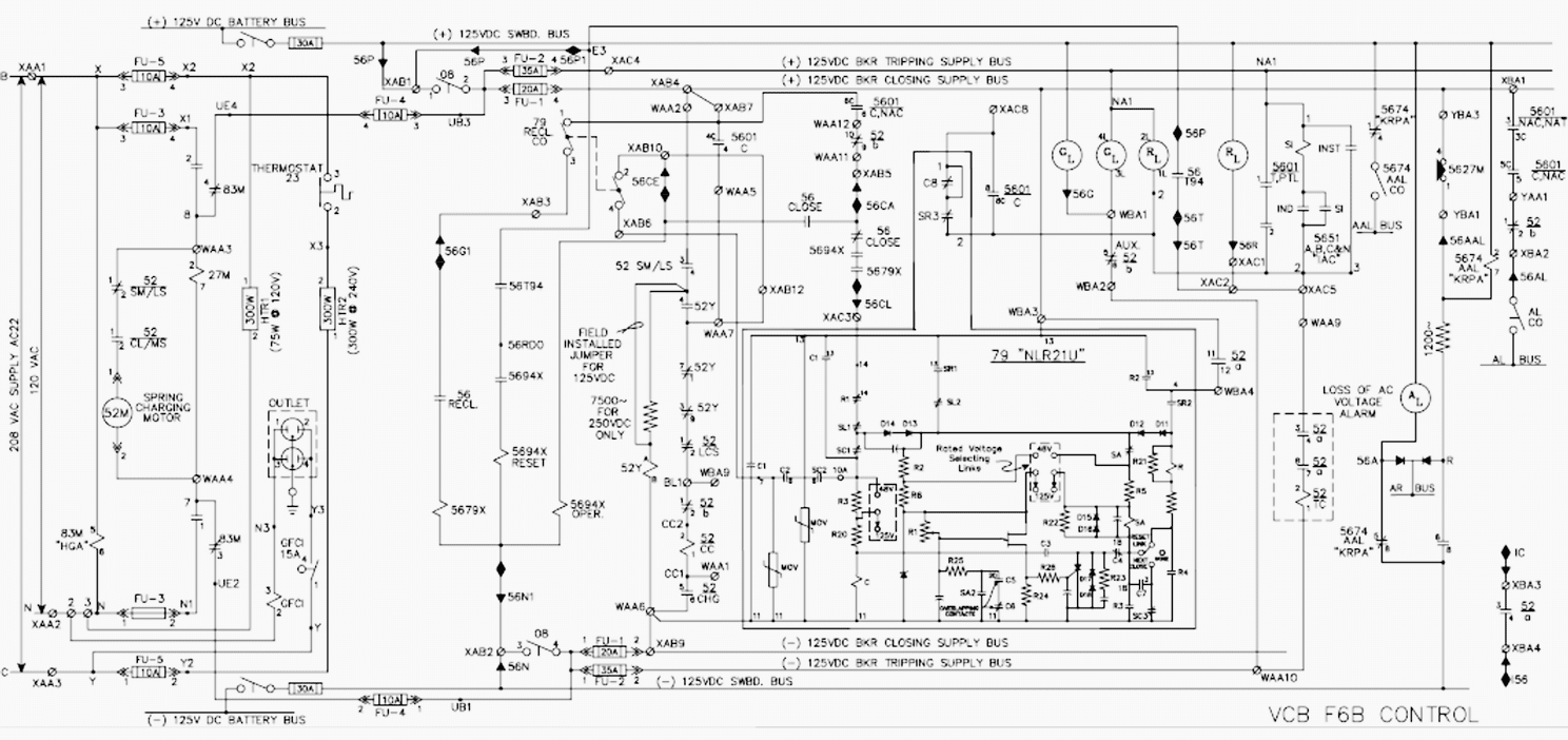
With an abbite k line circuit breaker the contact marked cps control power switch on the schematic is used to disable the motor charging circuit and would normally be closed.

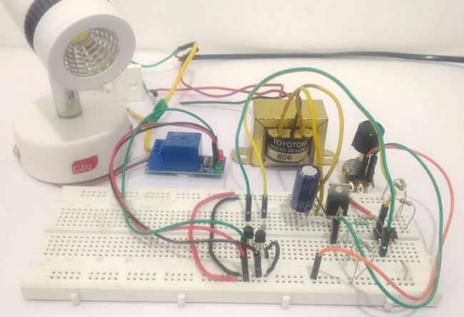
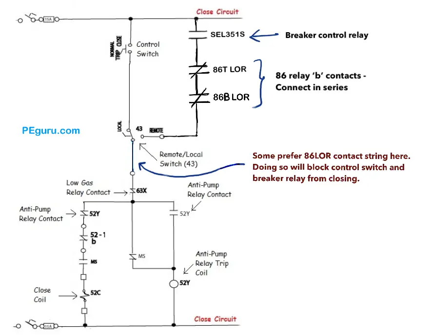
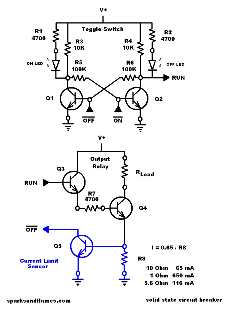
Simple circuit breaker diagram schematic. The primary purpose of the protective relay is. The complete schematic diagram of electronic circuit breaker is given in the image below. With the 52a contact in the trip circuit as shown in the scheme above once the breaker opens this contact opens too.
On the flip side with the breaker open the 52b contact in the close circuit is closed allowing the close operation when desired. The circuit breaker acts as a safety device in the same way. As shown above in circuit breaker schematic it is really simple and just a bunch of resistors capacitors and other stuff.
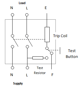
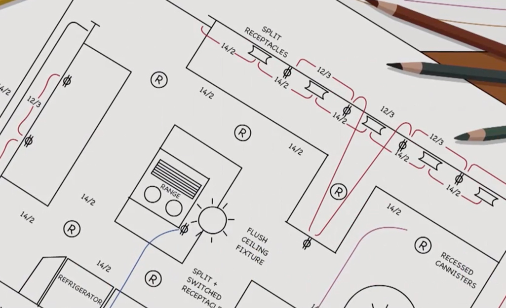
Next page for the residual current circuit breaker. Typically located on the cubicle door or at a remote control panel. When dealing with a large power distribution system a special type of schematic diagram called an electrical single line is used to show all or part of the system.
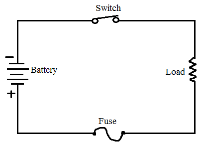
The basic circuit breaker consists of a simple switch connected to either a bimetallic strip or an electromagnet. Simple car circuit breaker schematic diagram 500x237 circuit and wiring diagram download for automotive car motorcycle truck audio radio electronic devices home and house appliances published on 17 mar 2014. Control voltage for electrical operation is provided to.
Abb circuit breaker schematic diagram. What is a simple electrical circuit simple circuit loop electricity simulation interactive flash animation to learn vocabulary like connecting wires interruptor or electrical switch bulb. Circuit breaker control schematic explained secondary disconnect.
When the circuit breaker is racked into a cubicle and is connected to control power the following occurs. The hot wire in the circuit connects to the two ends of the switch. The diagram below shows a typical electromagnet design.
This page describes a simple circuit breaker. The spring charging motor immediately runs. Board in houses are called mcbs miniature circuit breakers.
Figure 10 comparison of an electrical schematic and a wiring diagram. Circuit breakers that are used at the distribution. Figure 12 schematic of a cars electrical circuit.
Now no matter what the relays do the trip coil is isolated. Read further for the explanation of the same. Batteries resistors inductors capacitors switches or a model of such an.
But what actually happens behind all these.
 Electrical Print Reading Industrial Wiki Odesie By Tech Transfer
 5 Often Overlooked Tests For Power Circuit Breakers
 Industrial Control Basics Part 1 Contactors C3controls
 Motor Control Circuits Types Electrical Industrial
 Electronic Circuit Breaker Schematic Diagram
 Different Types Of Circuit Breakers And Its Applications
 Reading And Understanding Ac And Dc Schematics In Protection And
 Power Circuit Breaker Operation And Control Scheme Peguru
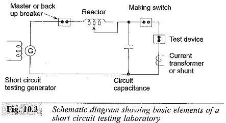 High Voltage Test On Circuit Breaker And Isolators Short Circuit
 What Is Fuse Different Types Of Fuses And Working

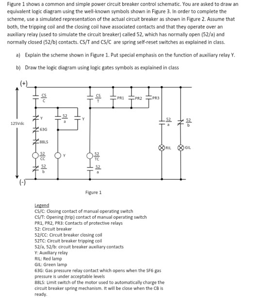 Figure 1 Shows A Common And Simple Power Circuit B Chegg Com
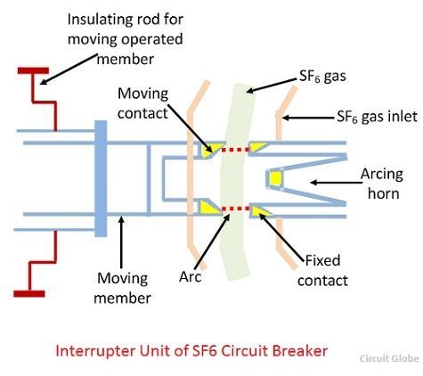 What Is Sf6 Circuit Breaker Construction Working Principle
 Password Based Circuit Breaker Circuit Circuit Diagram Projects
Electrical Circuit Breaker Diagram
 How To Install A Circuit Breaker The Home Depot
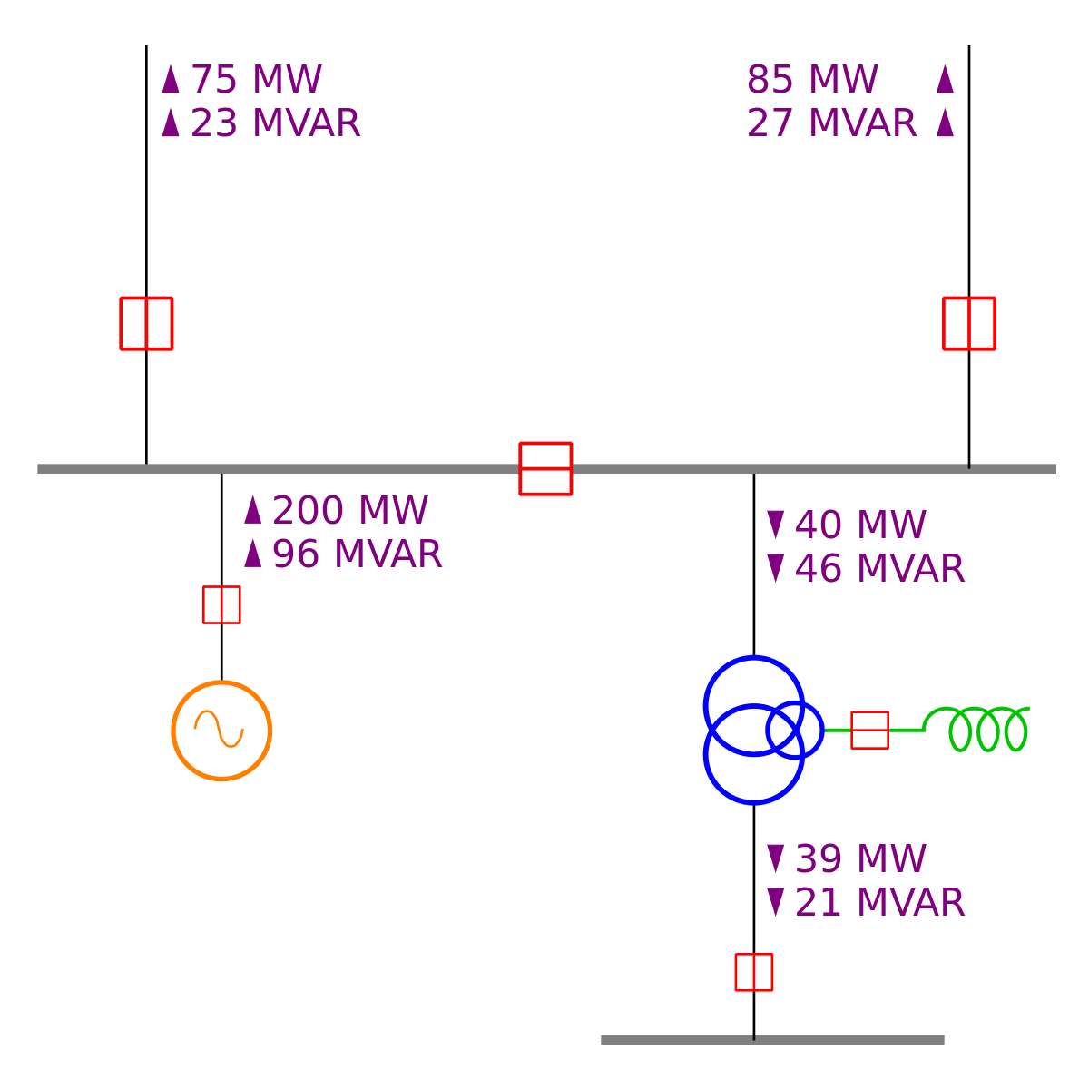 One Line Diagram Wikipedia
No comments:
Post a Comment