Diagram is a synonym of schematic. In some cases the schematic symbol and the wiring diagram symbol are the same.
V 2500 Digital Satellite Receiver Schematics V2500 Schematic
Schematic diagrams only depict the significant components of a system though some details in the diagram may also be exaggerated or introduced to facilitate the understanding of the system.

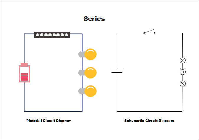
Schematic diagram vs circuit diagram. A schematic is defined as a picture that shows something in a simple way using symbols. Circuit diagram or schematic diagram does not show the position and distance of components. Many wiring diagrams also have a key that provides important information such as wire gauge and colors.
Schematic is a synonym of diagram. Figure 4schematic diagram wiring diagram or pictorial. Wiring diagrams are made up of two things.
As nouns the difference between schematic and diagram is that schematic is a drawing or sketch showing how a system works at an abstract level while diagram is a plan drawing sketch or outline to show how something works or show the relationships between the parts of a whole. Circuit diagram or schematic diagram not classified into single line or multiline diagram. Symbols that represent the components in the circuit and lines that represent the connections between them.
It is used to show how the circuit functions. Schematic circuit diagram a schematic circuit diagram represents the electrical system in the form of a picture that shows the main features or relationships but not the details. There mainly two types of wiring diagram are used one is single line diagram and another is multiline diagram.
In a schematic circuit diagram the presentation of electrical components and wiring does not entirely correspond to the physical arrangements in the real device. A simplified conventional pictorial representation of an electrical circuit. A wiring diagram is a type of schematic that uses abstract pictorial symbols to show all the interconnections of components in a system.
A diagram that uses lines to represent the wires and symbols to represent components. A schematic diagram is a picture that represents the components of a process device or other object using abstract often standardized symbols and lines. Wiring diagrams for circuits use the same labels as the schematic.
 How To Read Circuit Diagrams For Beginners
 Difference Between Schematics And Circuit Diagrams
 Wiring Diagram Everything You Need To Know About Wiring Diagram
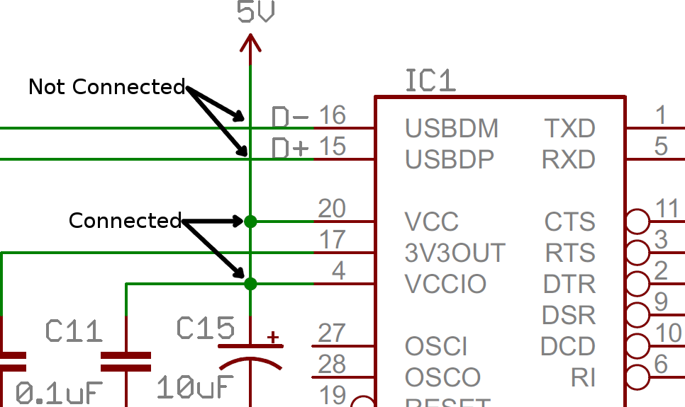
 How To Read A Schematic Learn Sparkfun Com

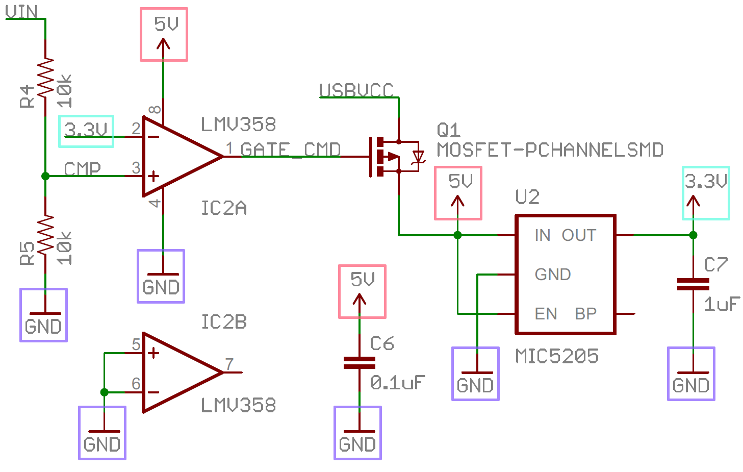
 How To Read A Schematic Learn Sparkfun Com
 10 Friendly How To Draw A Schematic Diagram Of A Circuit
 Htc Desire V Circuit Diagram Wiring Diagrams All
 The Schematic Diagram Of The V Blender Electrical System
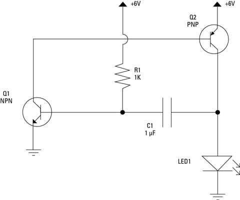
 Electronics Schematics Commonly Used Symbols And Labels Dummies
 Circuit Diagram Of The Main Distribution Board Download
 How To Read Circuit Diagrams Electrical Circuit Diagram
Free Taser Stun Gun Schematics And Plans
 How To Read A Schematic Learn Sparkfun Com
Physics Tutorial Circuit Symbols And Circuit Diagrams

:max_bytes(150000):strip_icc()/MontyRakusen-5c4df34cc9e77c0001d760bd.jpg)
No comments:
Post a Comment