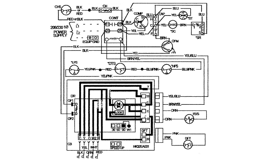
A wiring diagram is a simplified standard photographic depiction of an electrical circuit. This diagram is to be used as reference for the low voltage control wiring of your heating and ac system.
Simple Heat Pump Schematic
As they say a picture worth a thousand words.

Heat pump schematic diagram. Heat pump thermostat wiring a typical wire color and terminal diagram. It reveals the parts of the circuit as simplified shapes as well as the power and also signal links between the tools. As the name suggests a heat pump transfers or pumps heat from one place to another notice the use of the word pump heat is not generated but rather is moved.
While an air conditioner uses the process of refrigeration to only cool the central air conditioner will usually be paired with a gas furnace an. Heat pump wiring diagrams. Heat pump wiring diagram schematic collections of elegant wiring diagram for york heat pump.
Ac heat pump with variable speed air handler and single stage electric backup heat control wiring. Heat pumps are different than air conditioners because a heat pump uses the process of refrigeration to heat and cool. Variety of goodman heat pump wiring schematic.
As shown in the diagram you will need to power up the thermostat and the 24v ac power is connected to the r and c terminals. Circuitry layouts are made up of two points. Heat pump thermostat wiring chart diagram hvac the following graphics are meant as a guide only.
Always follow manufacturers instructions for both the thermostat and the hvac system. Heat pump wiring diagram schematic luxury charming lennox thermostat. C is known as the common terminal.
Additional articles on this site concerning thermostats and wiring can help you solve your problem or correctly wire a new thermostat. These two connections will ensure that there is power to the thermostat that you are operating. Always refer to your thermostat or equipment.
Symbols that stand for the parts in the circuit and lines that represent the connections between them. The color of wire r is usually red and c is black. Luxaire electric furnace wiring diagram new payne heat pump wiring.
The heat pump is very simple once you understand the basic concept and i promise you will after reading this. A wiring diagram is a kind of schematic which utilizes abstract photographic icons to show all the interconnections of elements in a system. New heat pump thermostat wiring diagram trane heat pump wiring with.
Thermostat wiring diagrams for heat pumps heat pump thermostat wire diagrams. New goodman heat pumps include various hvac equipment manuals to assist with installation replacement parts operation maintenance and more. Goodman heat pump package unit wiring diagram.
Always keep your goodman heat pump manuals handy so you can reference them as needed.
 Heat Pump Thermostat Wiring Diagram
 Schematic Diagram Of Experimental Rig Of The Heat Pump System
 Goodman Heat Pump Wiring Diagram Schematic Wiring Diagram E7
 Schematic Diagram Of The Single Stage Heat Pump Cycle Download
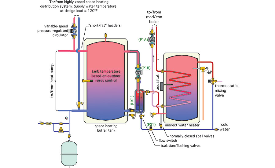 Hydronics Zone Combining A Water To Water Heat Pump With A Mod

 Figure 1 From Heat Pump Efficiency Improvement By Discharge
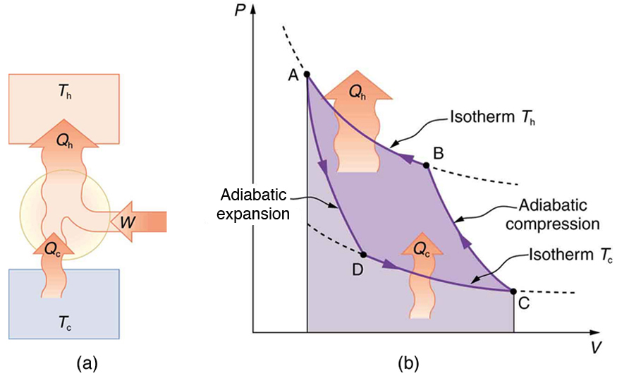 Applications Of Thermodynamics Heat Pumps And Refrigerators
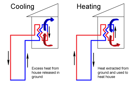
Geothermal Heat Pumps Renewable Energy World
 Troubleshooting Challenge A Florida Heat Pump Problem 2017 10
 Sv Series Heat Pump Installation Instruction Manual Spa World
 Schematic Diagram Of The Heat Pump Download Scientific Diagram
 Ground Source Heat Pump Nzeb
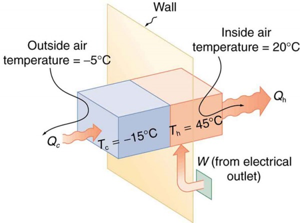 Applications Of Thermodynamics Heat Pumps And Refrigerators Physics
 Manuals Air Conditioners Boiler Manuals Furnace Manuals Heat
 File Schematic Diagram Of A Heat Engine Jpg Wikipedia
 Purdue University Hydrologic Impacts Group
 Sv Series Heat Pump Installation Instruction Manual Spa World
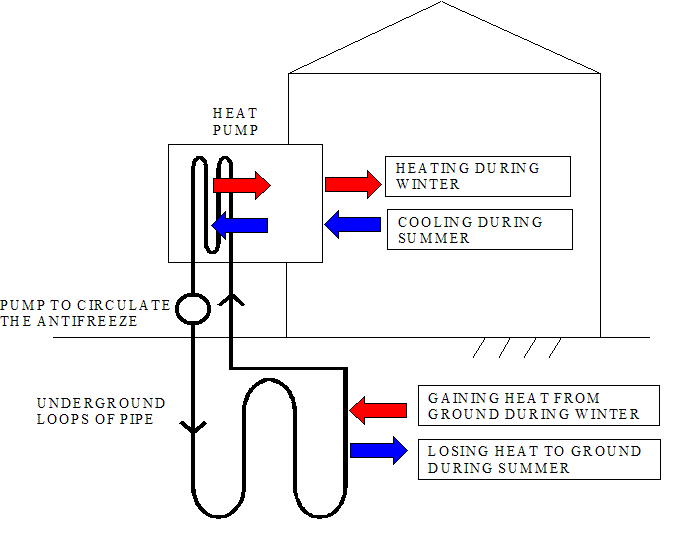 I Ve Heard About Geothermal Heat Pumps What Exactly Are They
No comments:
Post a Comment