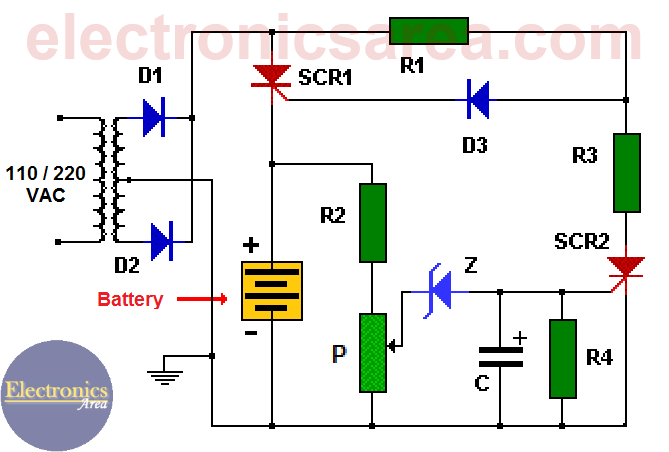
The main objective of our 12v power supply circuit is to control the voltage and current for the battery so that it can be charged in the best possible way. The complete schematics of this battery charger circuit are shown below.
 12v Auto Turn Off Battery Charger Electronics Area
Schematic of the simple 12 volt battery charger circuit car battery maintenance tips when the output is connected to the battery terminals the meter shows a higher reading depending on the current flow into the battery.
Schematic diagram of 12v battery charger. Decreasing the value of r2 effectively increases the final battery voltage by raising the current cutoff point. 12v battery charger circuit circuit diagram of the 12v battery absorb and float charger is shown in fig. C1 10000uf 63v.
It turns on the charger if the battery voltage is below the variable preset voltage 12 volt chosen here and turns off the charger if the voltage reaches 138 volt. Battery charger circuit diagram with parts list. You can use this circuit to charge 12v sla battery or 12v gel cell battery and so on.
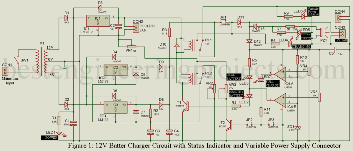
The capacitor filters the rectifier output to produce a clean 12v output. It is built around step down transformer x1 adjustable voltage regulator lm317 ic1 op amp comparator lm358 ic2 and a few other components. Always be careful to connect the charger to the battery in correct polarity.
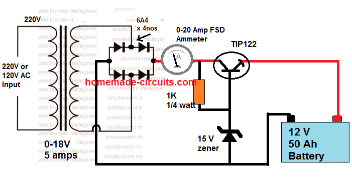
Positive to positive and negative to negative. At initial stages of charging the ammeter will read about 1 to 3 amperes. R1 032r.
D1 1n4004. So we want to show you a simple circuit for the charger when the battery is fully charged the charging automatically stopping this is a circuit of the auto cut off battery charger it has only one npn transistor such as c1815 for controlling the charging relay for cutting off this current path through the battery after fully charged. 7808 voltage regulator is used for constant supply to the operation of the circuit to cut at a required fixed voltage.
Circuit diagram of automatic battery charger this automatic battery charger circuit is mainly involves two sections power supply section and load comparison section. When the battery is fully charged the ammeter reading will be zero. The main supply voltage 230v 50hz is connected to the primary winding of the center tapped transformer to step down the voltage to 15 0 15v.
12v battery charger with auto cut off circuit diagram one 555 timer ic is used for detecting the voltage level and relay is used to disconnect the ac input. The main component of this auto battery charger circuit is a 555 timer which compares the voltage in the battery. As the battery is slowly charged the current slowly decreases.
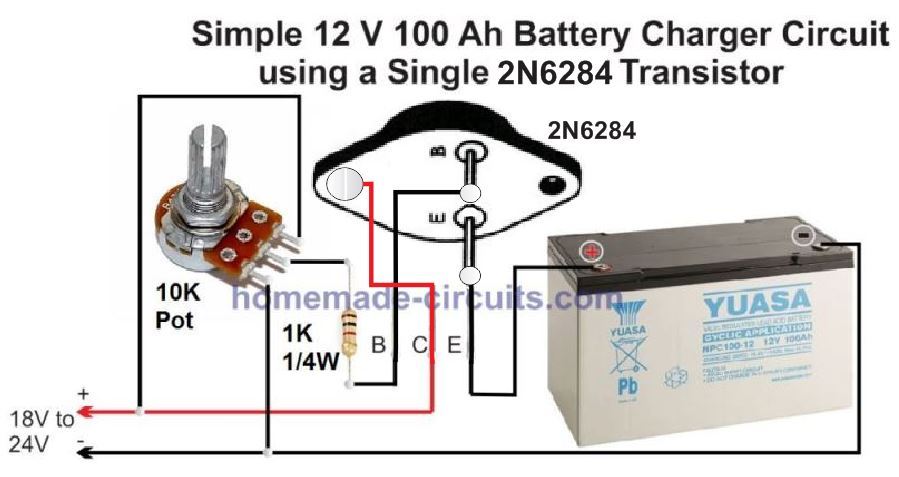
Simple 12 volt battery charger circuit diagram designed by using few easily available components and this circuit is suitable for different types of batteries needs 12 volt. Conversely a diode in series with one of the battery leads will reduce the fully charged voltage by about 07v.
 Battery Full Charge Alarm Circuit Eleccircuit Com
 12v Battery Charger 12v Battery Charger With Auto Cut Off
 Solar Charger Circuit For 6v Battery
 Pin On Batteries
 Motorcycle Battery Charger Power Supply Circuits
12v Battery Charger Circuit Diagram Using Lm317 12v Power Supply
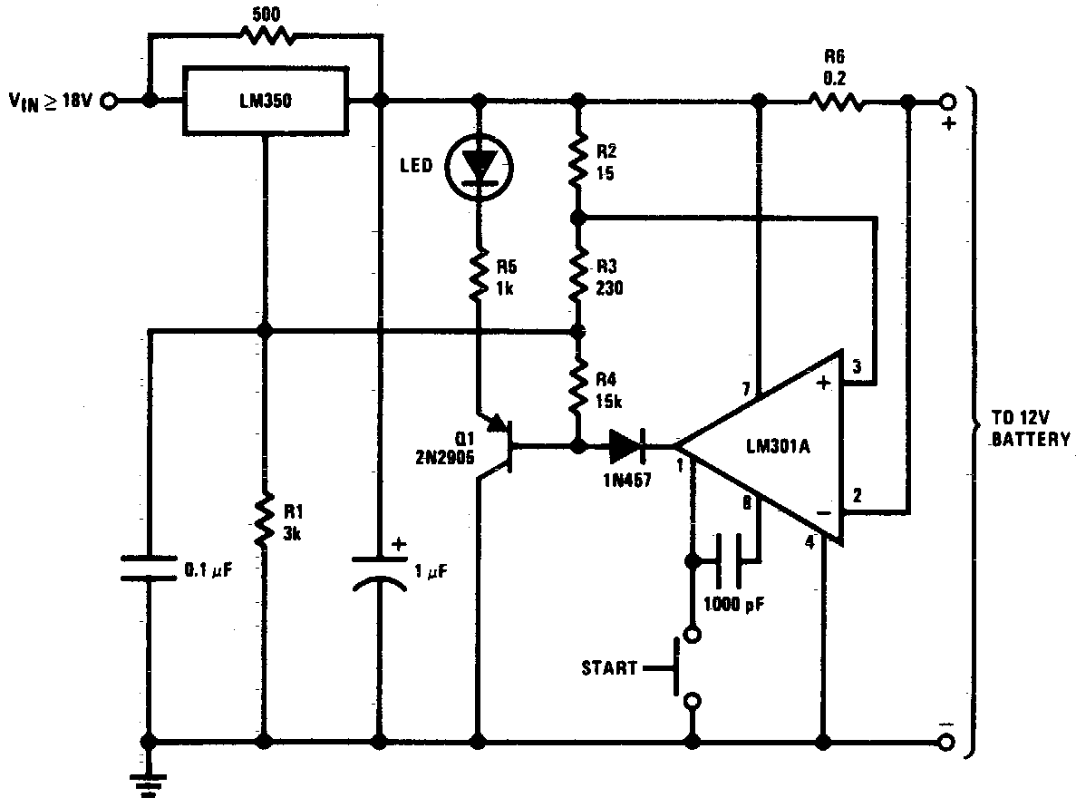
 12 Volt Car Battery Charger Circuit Schematic Eeweb Community
 Lead Acid Battery Charger Circuits Homemade Circuit Projects
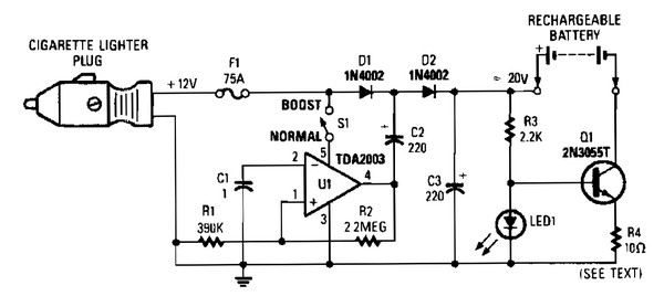
 Cigarette Lighter Battery Charger Schematic Circuit Diagram
 12v Smart Battery Charger Circuit Elektronik Elektrik
 12v Automatic Charger Auto Cut Off 3 Steps With Pictures
 12v Lead Acid Battery Charger Circuit Engineering Projects
 Car Battery Charger Circuit
 Automatic 12v Portable Battery Charger Circuit Using Lm317
 12v Automatic Charger Auto Cut Off 3 Steps With Pictures
 12v Battery Charger Circuits Using Lm317 Lm338 L200
No comments:
Post a Comment